The Kawasaki Ninja frame is pictured on the left. It is next to Hellboy in this picture, a past EVT project.
The motor being bench tested with its controller.
We used a Exascan 3D scanner from Creaform to scan our frame! This allowed us to accurately map mounting points on the frame, and define an envelope in which to place components.
An image of the scan in progress.
Using Creaform's software to clean up the scan data and transform it into a CAD model.
We used XALT 63 AH Lithium Nickel Manganese Cobalt Oxide (NMC) cells for the bike. They are arranged in a 24 series configuration, producing a nominal voltage of 88.8 volts.
This is an image of the battery module that we will be using on the bike. I worked on designing this module with one other team member over the course of a semester. The module provides four psi of compression to the cells via two compression plates on either end of the stack. This is recommended by Xalt to improve performance and safety of the cells. The tabs of the cells are connected via copper bus bars at the top of the pack. They are seated in polycarbonate for insulation purposes. The outer enclosure of the module is a combination of sheet and angle aluminum. The module is fully enclosed, providing maximum protection to the bike and the rider in the case of a thermal event. The temperature of the cells within the pack is maintained below the 60 C threshold by AllCell PCC-48 phase change material. This product is placed between every other cell in the pack, and absorbs much of the latent heat from the cells when the wax that it is infused with melts at 48 C.
This is a Soildworks simulation of the compression plate in the pack under typical load from the cells. The factor of safety and maximum deformation was found to be suitable for the application.
I ran drop test simulations on the battery modules in Solidworks to ensure that they would remain structurally sound in a crash situation.
Machining! Here I am using a die to cut threads on our compression rods. We could not use fully threaded rods because it would provide a puncture risk to the cells in the pack.
The fully finished compression rod with its drawing sheet.
Using the mill to locate an drill holes in the bus bars!
Using the rotating clamp on the mill to cut the 45 degree angles on the framing of the battery modules.
I machined the end plates of the battery module using the mill.
All of the in-house machining completed for the first battery module!
A local company, TCS Industries, was nice enough to help us out by doing the sheet metal work for the battery modules.
Our machine shop helped us out by using their CNC water jet machine to cut out the polycarbonate to hold the bus bars of our battery modules.
I used solid models that the team created from our Creaform scans to position the battery modules within the frame of the bike. By keeping the modules within the existing fairing, we could be sure that we would not encounter any issues with the modules scraping on the ground during hard cornering.
Here is another image of the clearance between the battery modules and the fairings.
The bottom module is held by two plates extending down from mounting holes on both sides of the frame. It is then braced by two aluminum tubes running from the back of the frame.
In the rear, the top module securely clamps to an aluminum rod running through two mounting points on the frame.
In the front, the module is held in place by two aluminum tubes running up from the bottom plate mounting mounts.
I ran Solidworks simulation under typical cornering loads to ensure that the mounting would remain secure during race conditions.
I ran another simulation to see how the mounting would react to a crash situation. I found that the structure would deform, but remain safe and intact.
Using known bike power and weight data, I constructed an Excel spreadsheet to calculate top speed and 0-60 times with various gear ratios.
We assembled the pack one cell at a time, while wearing high voltage safety gloves. After four hours, all the cells were in!
Here's the fully assembled pack before any connectors were added to the wiring.
In this image, the electrically insulating "fishpaper" was added to the sides of the pack, and a connector was added to connect the pack to our battery management system.
Here's the completed bottom pack before the lid was put on! The two plates welded to the side of the box are responsible for holding it to the frame. The loose wires are running to temperature and pressure sensors within the pack and still need to be integrated with the bike's on-board electronics.
Here's a picture of the two completed packs before they get put onto the bike!
Here's an image of the preliminary stages of battery mounting assembly. The top pack is held on in this picture only by the rod running across the top of the bike. The motor mounting you see below was completed by another team member.
RIT's Baja team let us use their tube bender to make the tubes we needed for our frame. This image shows the tube resting on its supports. I did this to make sure that the tolerances on the tube turned out correctly.
Here is a picture of both the top mounting tubes sitting in the correct place.
This picture shows all of the battery modules lined up where they are supposed to go before any welding work is done. This allowed me to make sure that everything would fit properly in the finished bike.
A local company, Mahany Welding Supply, helped us out a ton by welding endcaps onto our tubes.
Once the welding was done, I lined all of the tubes back up on the bike and drilled holes based on the proper alignment. This ensured that all of the tolerances would work out correctly.
Bolting on the bottom battery box!
Both batteries securely mounted on the bike!
Right before we were about to have first drive, the front brake's banjo bolt sheared. I made a new one in the machine shop using some spare steel stock.
Once the batteries and motor were in place, the electrical team could wire everything up and we could begin testing!
After confirming that all systems were functional on the bench, we headed out to the parking lot for first drive!
Our professional rider, Karl, rode the bike around for the first time! After ironing out a few bugs, we were ready to take REV1 to race in New Jersey.
Anticipation was high as we waiting for the bike to charge the night before the first race!
An awesome shot of Karl guiding REV1 around the track!
The team was super excited after finishing both of our races on the weekend! We're looking forward to the improvements that the new year brings, as well as starting design work on REV2 in the near future.
gLike
REV1 Electric Superbike (EVT)

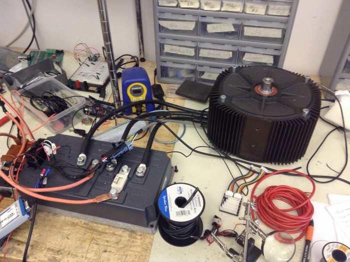
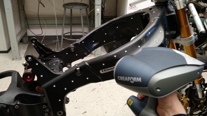
I built an competition electric motorcycle with the RIT Electric Vehicle Team during my first two years at school. We used a 2005 Kawasaki Ninja ZX6RR frame, a 7-57 motor from Zero Motorcycles, a Sevcon size 6 motor controller, and 24 Xalt 63 AH high power Lithium Nickel Manganese Cobalt Oxide (NMC) cells. My contributions include creating an excel spreadsheet to calculate the gear ratio for desired performance characteristics, design of safe and high power battery modules to house the cells, and framing to mount the battery modules to the bike. We competed in the eMotoRacing varsity challenge at New Jersey Motorsports Park in summer 2015, and were the only collegiate team to successfully make it to and complete the race!

View Website
Available
Full-time
Jeffrey Botticello
Mechanical Engineering Student Rochester, NY