
First test on the magnetic loop.

Capacitance measurement at the highest capacity, aim was 50 pF.

Capacitance measurements, here the capacitor is at it's lowest capacitance. Almost zero, so a very good design.

Further assembly.

Assembly of the capacitor with threaded rods and 3D-printed sideplates.

Milling proces via turning table to obtain the round edge.

Milling proces for the capacitor plates.

Rough cut outs for the aluminium capacitor plates.
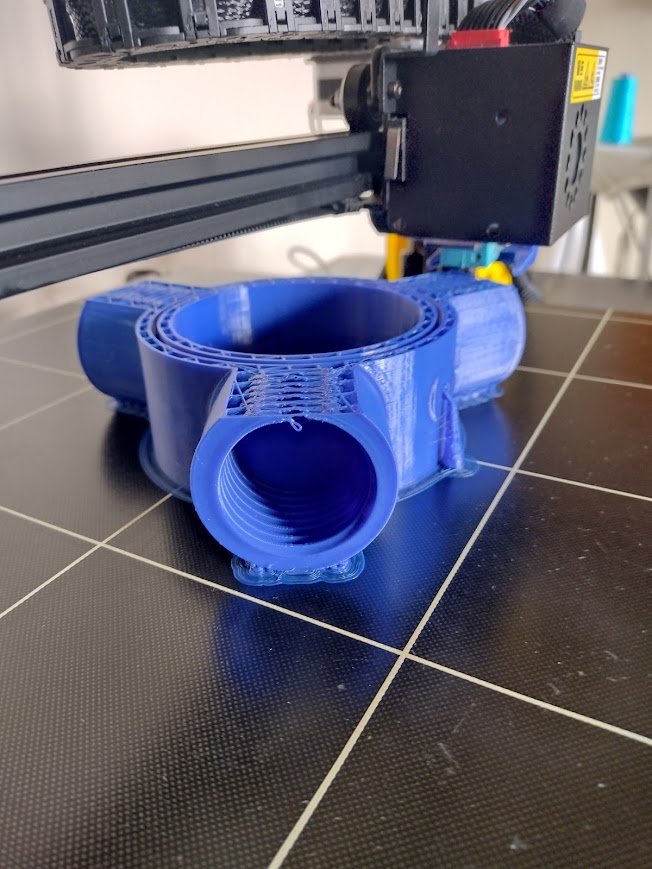
3D-printing a part of the tripod structure for the magnetic loop.
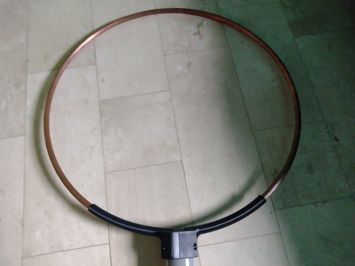
Upper part of the magnetic loop.
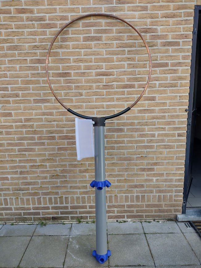
Assembly process of the magnetic loop.
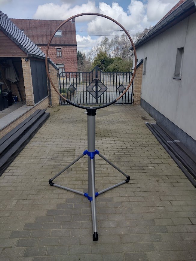
Full structure assembly of the magnetic loop.
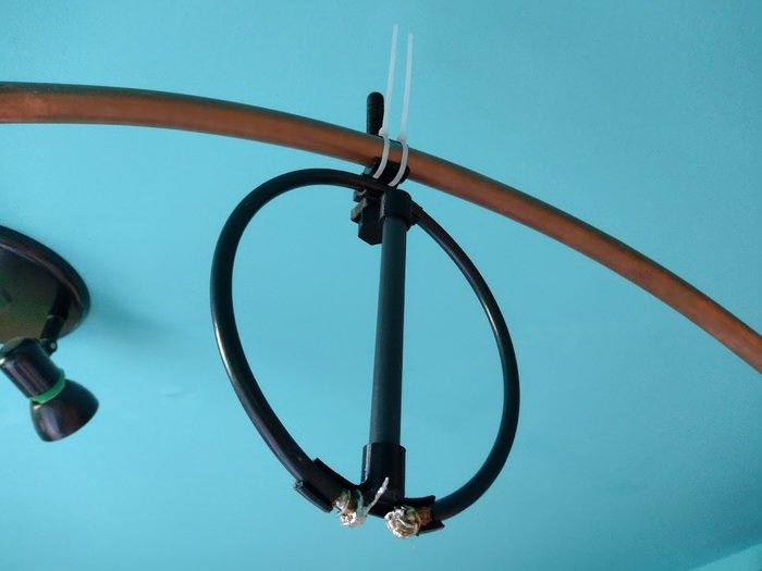
First iteration for the coupling loop.
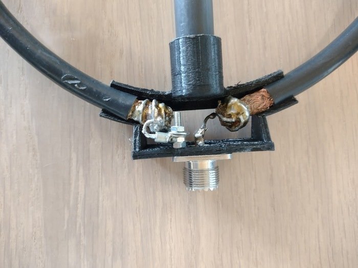
Second iteration for the coupling loop, with a PL259 connector.
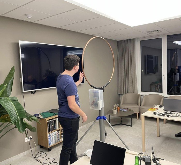
Me presenting the design and tuning process to the team members of the local radioamateur club (ON6ZT).
gLike
Magnetic Loop With Butterfly Capacitor 0-50 pF
The butterfly capacitor project started with the need for a variable capacitor to use on a magnetic loop for 20 m to 10 m amateurradio band. The capacitor consists of several machined aluminium plates (Milling operation). This capacitor will be driven by a steppermotor.