
I used femm (finite element method magnetics) to simulate the performance characteristics of the motor. This image shows the material, magnetic, and circuit definitions of my motor.
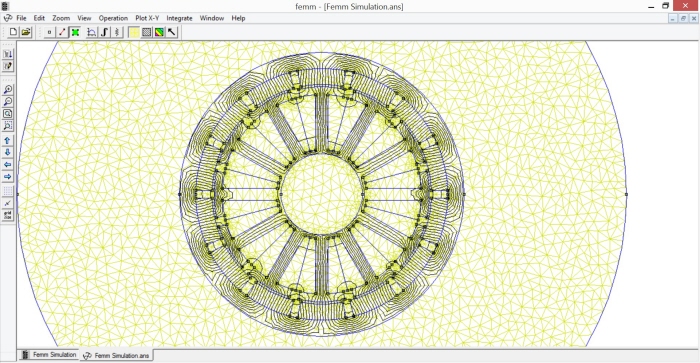
The femm simulation determined that the motors would produce about 12 nm of torque at optimum conditions. I expect the real value to be lower.

I used Matlab to build a simulation of heat transfer within the motor. The simulation assumes a constant current of 10 Amps through the motor until the battery is completely depleted. I found that the max temperature the motors could reach would be 100 C. This is acceptable because it is below the Curie point of the N48H neodymium magnets that I am using.
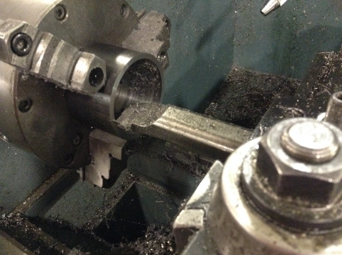
Boring out the steel to make the rotor of the motor.

Tapping the holes that will attach the aluminum end caps to the steel rotor.
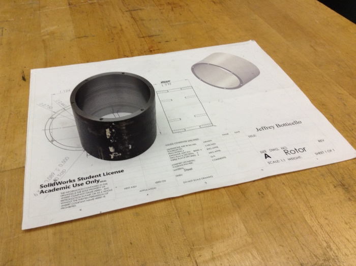
The completed rotor with drawing!
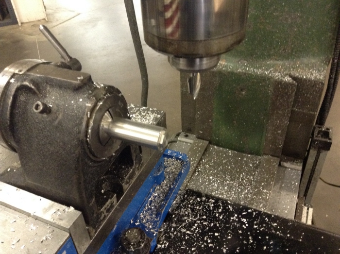
Cutting hex heads into the shaft so they can be easily tightened onto the truck.
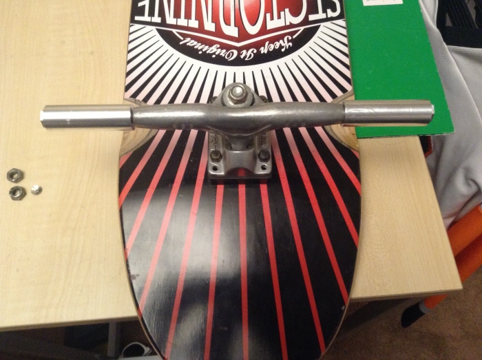
The completed shafts fitted onto the trucks!

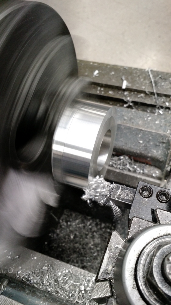
Turning the end caps out of a large aluminum rod. I first drilled the screw clearance holes all the way through the rod, then bored out the stock to the proper size. This allowed me to use the parting tool to cut four parts off of the same piece of stock.
Turning the aluminum endcaps.
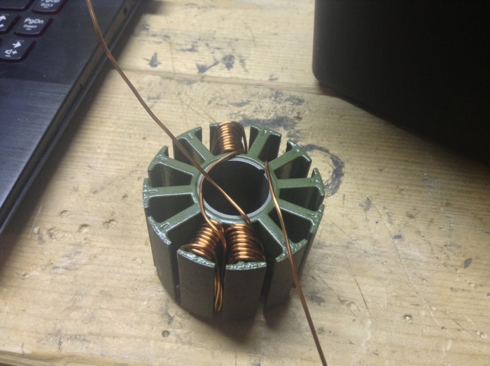
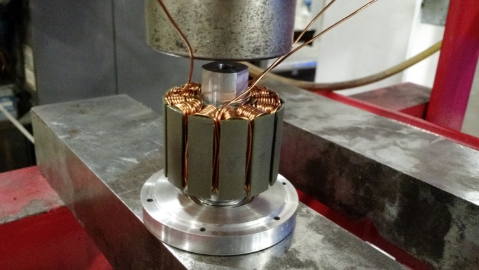
Winding the first phase of the motor. I used 10 turns of 18 AWG enameled copper magnet wire.
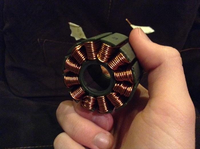
The completed winding!
Pressing the shaft into the stator.
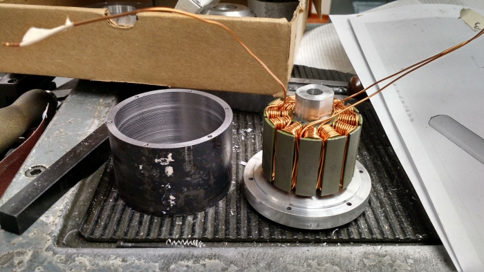
The steel rotor next to the stator-shaft assembly.
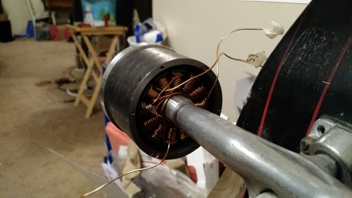
A shot of the motor secured to the longboard truck. One of the endcaps is off in order to show the coils around the stator.
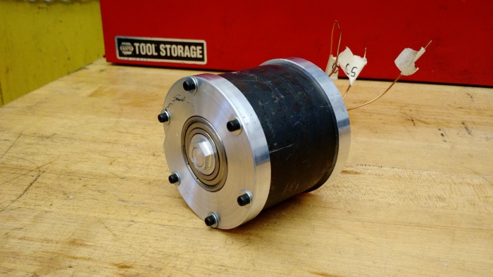
The fully assembled mechanical structure of the motor! Still waiting for the magnets to come in.

To align the magnets in the rotor core for gluing, I used pieces of solder that happened to be the right thickness to provide even spacing.

Here's what the rotor looks like with all of the magnets glued in place!

I epoxied hall effect sensors in the appropriate slots of the stator and connected power, ground, and signal wires to them to hook up to the motor controller.

I have the motor all together and mounted onto the longboard, but when I try to test it the motor controller throws a hall effect error. I currently believe that I accidentally swapped a power and signal line on the sensors. I need to pull the motor apart to check this, but I don't currently have access to the tools I need to do that. Hopefully I'll be able to make a trip back to school from my internship soon so that I can keep this project moving.
gLike
Electric Longboard Hub Motors (Personal)
At the beginning of my 2nd year at RIT, I decided that I wanted to build an electric longboard using custom built in-wheel hub motors. I was inspired by Jed Storey's electric longboard at mitrocketscience.blogspot.com, and learned a lot about the technology behind hub motors from http://www.instructables.com/id/Make-Your-Own-Miniature-Electric-Hub-Motor/. In my design, I hoped to make a motor that would look more like a traditional longboard wheel, and that would easily mate with the existing truck.
Currently I am in the process of machining out the parts for the two motors that I plan on making.