
Drilling the hole for the load cell bolt.
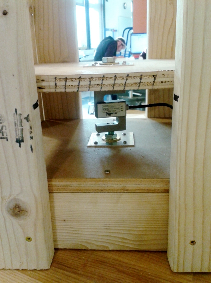
The 'S' shape is the load cell connected to the two pieces of ply by bolts. The bottom ply is stationary and the top ply is only held in place by the bolt in the load cell. This ensures that all of the force generated by the tank is applied through the threads of the load cell.

A view from the top looking down on the ply that the tank rests on.

This line plugs into our data acquisition board (DAQ) and allows us to get a reading from the load cell.

We didn't have quite enough wood to make it all the way around with the support bars...

The load cell stand functioning on site.

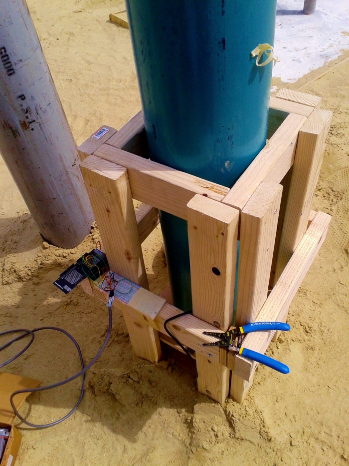
The stand with the DAQ system.

Next to our test stand for the MKIII hybrid rocket.
gLike
Load Cell Stand for a K-size Nitrous Oxide Tank
For the Boston University Rocket Propulsion Group's MKIII hybrid rocket motor, we needed to find a way to measure how much nitrous oxide we had put into the rocket. To solve this problem, I used a load cell rated to 500 lbs and built a stand to hold the cell and the tank. The stand is built out of pine and I added 1/8" aluminum sheets where the load cell bolts go through the plywood for added support and to dissipate the force over a larger area.
View Website