
My order of cheap mono 3/8" mini plug jacks has arrived. These are switch jacks, so I will simply clip off the switch lead to avoid confusion while soldering.
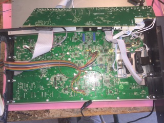
Disassembling the minibrute is fairly straight forward. There are screws on the bottom perimeter which need to be removed. There are an additional three screws on the rear panel which need to be removed to allow access to the larger of the two PCBs.
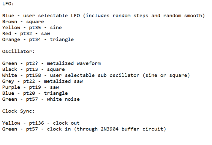
These are the nodes that I have soldered to for various waveform output. Each of these nodes connects to each of 14 total jacks. I used a common ground for all jacks and soldered it straight to the PCB ground plain.
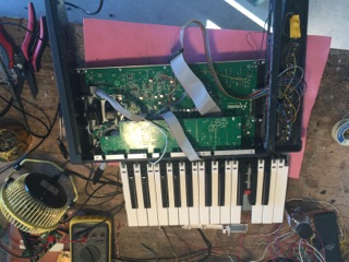
Using a scope I am able to locate each of the wave forms where I want to solder leads to. They are each located at various test points labeled such as PT35, etc. I use a ribbon cable and fan it out to extend to the various test points.
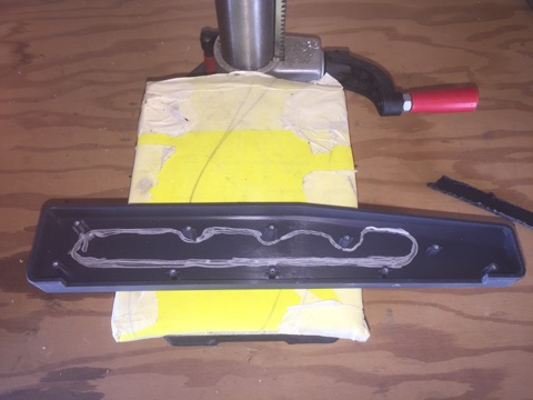
There is an inner side panel and an outer rubber side panel. This is the inner side panel, which makes mounting jacks a little tedious. Making sure I can clear all the screw slots that hold the sides onto the chassis, I mark an area which I can cut out with a dremil tool.

Alternative view of side panel.

Inner side panel is cleared so that I can work the jacks through to the exterior side panel.

All the jacks are in. I placed them inside before soldering. The leads on the pcb are not very hefty solder joints, so I want to minimize any additional stress while working with them.

View from inside the side panel where I have installed the jacks. There is some wear where I used a dremil tool to make the panel thinner so that I could fit the screws onto the front of each jack. Not pretty, but this cosmetic flaw will not be seen when re-assembled.

(Schematic courtesy of leafcutterjohn.com) Clock sync is effectively using a clock input signal to trigger the tap tempo portion of the Minibrute circuit. To add a clock sync input, the following circuit was used.

An NPN transistor and Diode circuit that I am using to buffer the clock synchronization input.

Circuit for the clock sync input. I will shrink wrap it, to avoid any shorts when placing it back inside the cramped enclosure slot.

Workbench with Oscilloscope, DMM, Solder Iron, etc. Note that the keyboard needs to be removed. It is not tedious to remove and re-assemble it back into the enclosure.

Soldering the leads to their respective jacks.

I used a ribbon cable to keep the wiring footprint as small and tidy as possible. Also the thin wires work well for soldering to the test points.

The first mod. Testing reveals two faulty outputs. I will need to further inspect the pcb and the jacks to find the faults.

After re-assembling the chassis I tested the Minibrute against my larger Modular synthesizer. I found that the random sine LFO was not working and the Triangle jack was broken when I installed it. When I disassembled the Minibrute I found two faulty jacks. I replaced them and now they work great. I also made a few additional mods while inside. I added a "metalized" saw output and I added an LFO output for which the output waveform can be selected on the top pane. This is where I can access the smooth or square pseudo random LFO signals.
After debug, everything works great. (The clock output is very weak, but the signal is present and will trigger my SimpleSeq module if I first patch it through the gain stage of my .com Standards module.) The sync input circuit works great.
gLike
Aturia Minibrute Mod
Arturia Minibrute Modifications:
Oscillator Outs for:
* Noise
* Saw
* Metalized Saw output
* Triangle
* Sub Oscillator Output
* Square
LFO Outs for:
* User select able output for Random stepped and Random smooth LFO waveform.
* Sine
* Triangle
* Saw
* Square
Clock Synchronization:
* Clock sync input (requires additional circuitry)
* Clock sync output