
I have drawn up the following schematic which I will work from. It includes power supply decoupling, midi opto isolation, and a gain adjustment on the output stage to bring the line level output up to modular standards.

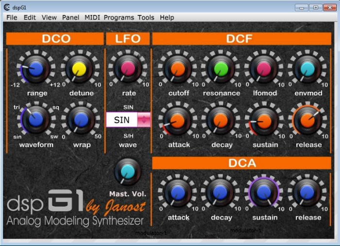
There's a nice GUI available for sending midi CC control message to the device. I can use this or I can map CC control messages from a midi control keyboard. I will probably choose the latter option, but it will be nice to test against this gui option for starters.
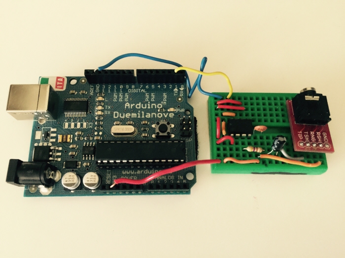
Arduino based test. I simply ran the Arduino Midi example sketch to see if I could hear something. It works, though I still need to test it against Control Change settings, so as to hear how the DSP sounds and what it's capable of.

This is a diagram of the internal structure of the DSP-G1 IC. Also, it includes a list of midi CC#'s which are supported.

And since this is a digital project and the DSP-G1 is controlled by MIDI, I thought I'd design a Max4Live patch just for kicks. This might also come in handy for automation.

The DSP-G1 ic can handle a maximum of 3.3 volts power. I will be sourcing power of +5v from my power supply, so I need a voltage regulator to keep the voltage under 3.3v. I have chosen to use the LM1117T to perform the voltage regulation in my circuit.
View PDF
View PDF

Pin configuration of the LM1177 voltage regulator IC that I will be using to step down the voltage from +5v to 3.3v. This is a fixed voltage regulator. Aside for the decoupling caps, there isn't any additional circuitry required.

I have designed a pcb trace with plans to etch it onto a copper clad pcb, but upon building the same circuit upon breadboard, I couldn't even get any sound from the DSP. (I suspect the photo couple IC) I thought perhaps I had roached the DSP IC, but upon moving it over to an Arduino (TX pin) based midi sketch, I was able to hear sound. It was clicky and noisy, but that's likely because I haven't adjusted any of the internal envelopes upon the dsp via control change (CC#) messages.


I have used a TL072 op amp to increase the gain of the line level output, from the DSP out, to modular +-5v level output. This audio output will be ac coupled as well. The other side of the op amp will be used to isolate an LED midi status indicator, thus eliminating the need for the hex inverter IC as seen on my original schematic.

Breadboard test and circuit debug. I'm going to take my chances and omit the opto coupler from the circuit. I should be alright, my midi controller is opto coupled on that end.

Revision 1 of the breadboard design. It's much simpler now, with fewer components and down to 2" x 2.5" in scale. Next, I will etch a pcb using the positive photo resist method.

A few of the traces had shorts, particularly the capacitor locations. An exact-o knife can be used to ensure the separation between pads. It's a good practice to inspect any board before committing it to solder and components.


Fellow Muffwiggler Cranium has requested that I build him one of these boards.

Completed board for Cranium. I just need to receive a +3v regulator in the mail, and then It's all ready for the panel.
gLike
DSP-G1 - Paraphonic Midi Synth Module
A paraphonic module for modular synth. At it's core a pre-programmed dsp chip is is utilized to model an analog synthesizer. The module can be controlled via a midi cable and a GUI for setting CC parameter values.
Features:
· 15 DCO, 24db DCF, 2 ENV, 1 LFO
· 5 voice paraphonic voice structure
· 44.1KHz 16-bit Delta-Sigma DAC
· 19 parameters controlled through MIDI-CC
· 3.3v power regulation, down from 5v power supply voltage.
- 10v AC coupled audio output (for use with modular synth standards.)
- LED indicator for MIDI RX activity.