
I located an old copy of the Synsonics service manual on the internet. They don't make 'um like this anymore. The notion that someone would actually repair an electronic device was still the norm in 1982, I suppose. A great resource for making modifications to the original design. Included is a detailed schematic to reference while working.
View PDF
View PDF
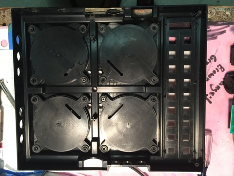
Inside the top face of the drum machine. Notice the four round piezoelectric pads. Since I will never use these drum pads, I don't hesitate in the least to clip the leads to each of the piezos so that I can use the same cable harness for connecting four of the six total trigger inputs.

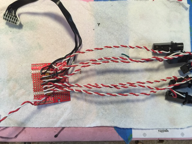
Here you can see the cable where I clipped the leads. There are 8 leads in all. Four piezo trigger inputs, and four grounds.

Since I don't know the exact piezoelectric transducers used, I decide to start with the assumption that they generate around .9 volts when struck. Since I plan on triggering the drums with anywhere from +5 to +10 volts, I plan to use a voltage divider circuit to drastically scale down the input trigger voltage. A diode is used to half wave rectify the incoming trigger and to rule out the probability of any negative voltage.

Having made some calculations, I have bread boarded a single jack scenario, which I can debug and modify as needed.

By removing the battery chassis, I have made room to squeeze in some trigger input and audio output jacks.

Rather large battery chassis has been removed to make room for the eight, 1/4" jacks. I later would use this as a dish for mixing my epoxy, which I used to glue the jacks to the inside of the case.

There's a five pin MIDI style DIN jack on the side of the unit. The Synsonics manual specifies what each of these pins can be used for. I will modify a midi cable to access these nodes for a HH accent control voltage input, and a separate BD trigger input. These are on pins 4 and 5 with a ground provided on pin 6.

This is the circuit I used to trigger the synsonics where the piezo pads used to be. It's just half wave rectification to ensure the trigger signal polarity is positive polarity. The caps eliminate trigger noise by decoupling the the triggers.ption Here
The final circuit only requires a diode, and a capacitor shunt to ground, which decouples the trigger input voltage enough to eliminate unwanted audio artifacts at the attack portion of each drum tone.

Using a drill press, I make some holes where I plan on placing the input trigger jacks. I add two more holes on each side which I will use for audio output jacks for the drum voices.

PCB view. The top portion is the underside of the user programmable touch panel.


Working the jacks, wires and perf board into place.

Jacks are all in. I couldn't get the jack threads to clear the enclosure, so I used epoxy to fix them into place. Good enough for a mod on a 50 dollar drum machine I suppose. There is a tiny perfboard circuit/hub where I have decided tie in all the trigger jacks to the main pcb.

Here I have soldered in some leads which will provide individual audio outputs for each of the drum sounds. This feature will be very useful in that I will be able to not only control the volume of each drum sound, but also with each drum isolated to its own output, I can route each voice through various filters or effects as desired.

Side view. Notice the two 1/4" jacks. They are offer individual snare and individual HH audio outputs.

On the alternate side, I have placed individual output jacks for Tom 1 and Bass drum.

Top view. After fitting everything back inside the enclosure, everything tests functional.
gLike
Mattel Synsonics Drums - CV Mod
Synsonics is a really fun, old school analog drum machine. I picked mine up off of ebay for 50 bucks. That's a lot of analog drum for 50 bucks.
Mod Includes:
* 1/16th rate clock sync output jack.
* HH trigger input jack.
* Tom 1 trigger input jack.
* Tom 2 input trigger jack.
* SD input trigger jack.
* HH audio output jack
* BD audio output jack
* SN audio output jack
* Tom 1 audio output jack
* I have also replaced a capacitor from 1uf to 10 uf, which the manual suggested would reduce the infamous power hum noise of this module.
* The pot for changing the pitch of the Tom sound was completely shot, so I replaced it.