
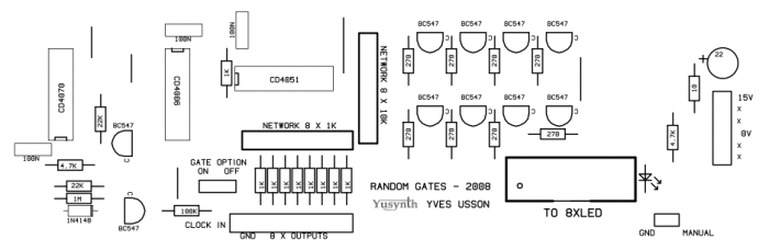
Schematic of the YuSynth circuit. Simple and elegant as usual.
View PDF
View PDF
Since I don't silkscreen any image at the top of the PCB, this image will aid in figuring out where to place components before I solder.
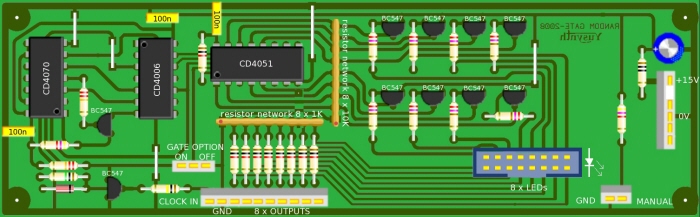
Another useful reference. "A picture is worth a thousand words."

I have invested in some diamond tip 1mm bits in the attempt to break fewer of them when drilling components holes into the PCB that I etch. I'm hoping these will be a little stronger than the typical carbide Dremil type bits I have used in the past.

Etched PCB, Transparency Image, Paper copy. As warned on the YuSynth site, many of the IC addressing traces are very close together. I was confident that I could cut through the shorts in the traces but it's just too much clutter. It now seems I will need to order a proper panel from bridechamber.com if I am to continue with building this module.

A proper pcb has arrived from Bridechamber. Many of the leads on the circuit trace were just too close for me to etch them properly. Others may have better luck but my transparency prints have a bit of ink around the edges in spots which seems to prevent some of the higher detail etching. I also needed to order a CD4051 which I didn't have on hand.

An easy breezy logic module. I see why the electronics industry went digital.....sort of....
On a side note, the 1k and 10k resistor arrays seem to have simplified this circuit considerably. I'll have to work some of those resistor networks into my own designs, seeing as how certain denominations 10k, 100k.....etc. are commonalities to working with the voltages and currents that I do.....These resistor arrays are obviously intended to accommodate a more digital process, yet I could see some use for them with backward compatible single sided pcb trace designs.

Connections for LED's, Jacks, and Switches. There is a momentary push-button switch as well as a toggle switch.

Under test, I discovered that gate #2 was not working. After replacing a faulty transistor, all is fully functional.
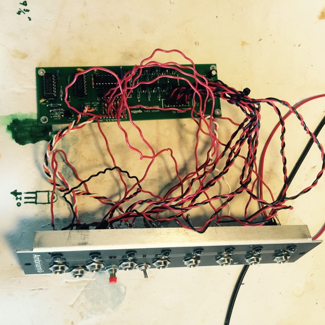
A mess of wires to finagle with.

Since I have re-purposed the panel from the Ardcore Xpander, I simply need to drill three new holes. Pushbutton, Switch, and Clock input jack. They just barely fit.

Cable ties!

Suggested panel layout. I'm going to re-purpose the Ardcore Xpander panel from a previous build. (The FTDI chips on the Arduino Nano boards no longer work under Windows, (long story).) What I will need to do is to add a gate in jack, and the two switches.
gLike
Random Gates - Module
This YuSynth.net circuit contains three main parts : the clock input built with Q1, the pseudo random sequence generator built with Q2, U1 and U3; and the addressing and output stages built with U2 and Q3 to Q10.
The core of the module is the pseudo-random sequence generator
Status: In Progress