
Advert for the original Steiner synth module. The unit employs it's own power supply, rather than using a power supply from a modular system.
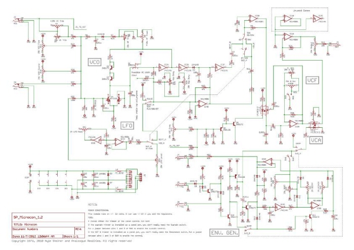
I've no idea why this power supply schematic based on the original, is +12v and -10v? I'll have to do my homework on this project.
View PDF
View PDF


Ouch, 10 $ each for the two Vactrols.


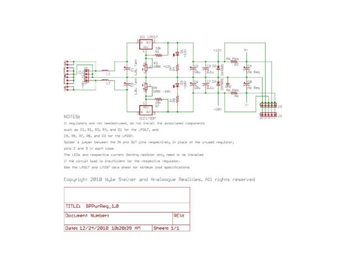
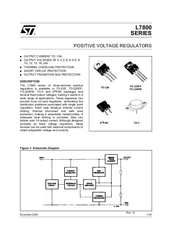
A very basic PCB trace that I made for stepping the voltage down from +-15v to +-12v. It's decoupled from the power supply and snaps between the power supply connector and the PCB power header. This should be interesting.

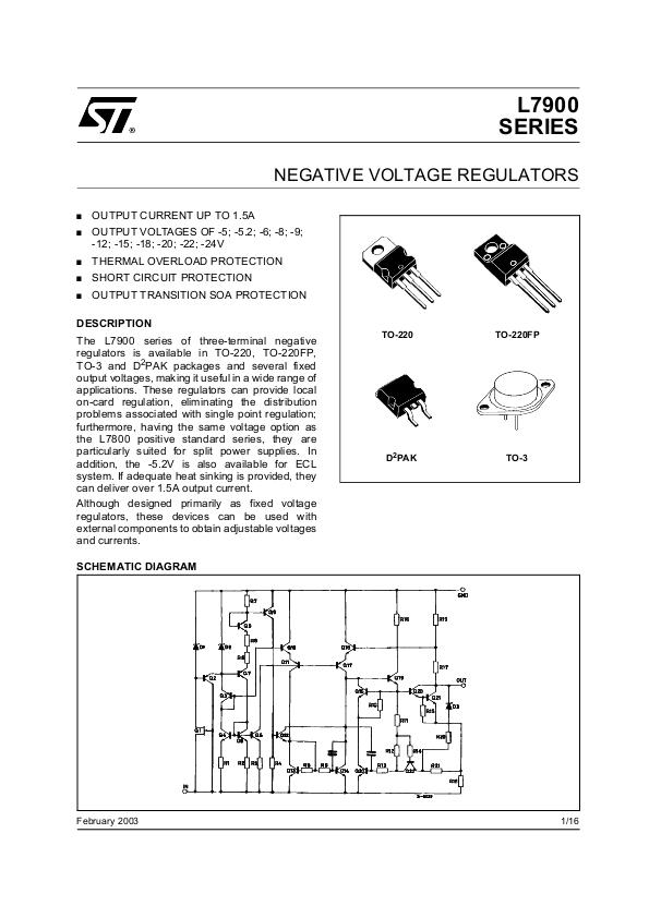
Etched the PCB without any major issues. Yet, upon testing, I measure the voltage and get a +12v reading on the positive rail output. When I measure the negative rail, I get a reading of -14 volts. I didn't have a load attached to the converter pcb, so that might very well be the reason one of the regulators didn't work properly. Further inspection is pending.

Vreg side view. 15v input at left header, 12v output at bottom header.

Vreg top view. After debugging the -12v rail of the voltage regulation pcb, I've determined that I was sent faulty parts. I'll have to be more careful about what I order from Asia, on Ebay. Sometimes I get a batch of parts that are consistently faulty. Anyhow, I'll solder in the replacement regulator when it arrives.

The voltage regulation board acts as a sort of go-between adapter. Indeed the -12v regulator I was using was faulty. I have soldered in the new one, and I now measure -12v.

Trimmer pots have arrived. 25k each. Still waiting on a shipment of capacitors and Photometers to arrive in the mail.

A MOTM panel face from which I can reference while planning my own. I have ordered a double 5U panel from Synthesizers.com that I will use.

Just waiting for an RF transistor to arrive so as to complete the components population of the pcb.

There are two switching jacks and three non-switched jacks incorporated. There are 3 x 2m ohm linear pots and the rest of the pots are all linear 25k ohm. Lots of twisted pairs in this build. I've even got a nice blister on my thumb from all the wire work.

Most of the jacks and pots are soldered to their respective nodes now. I'm just waiting for 8 switches to arrive so that I can wrap this project up. The switches are of the spdt and dpdt variety.

In test. I can hear the filter working, but no oscillator just yet. I'll need to trace through the circuit with my scope to find out why I can't trigger the envelope to hear the oscillator. Yesterday, I could hear only the the oscillator and no filter, but today it's the opposite. I had made some changes to eliminate some of the switches and pots, so as to fit everything into the panel.


gLike
Steiner Microcon - Synth Module
Monophonic Synth Module:
- Runs off of +-15v power supply
- VCO
- VCF
- Envelope
- CV IN