
The DG413 is an IC which can be used for switching applications. I have chosen it in place of a 4000 series switch because it passes AC analog audio signals.
View PDF
View PDF
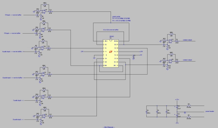
Rough draft of the design approach. Includes power supply decoupling circuit.

TL074 Op Amp Pin I/O. This op amp is used to drive the audio inputs through to the switch IC.

TL072 dual op amp pin I/O. This op amp is used for the two audio outputs which the switch IC feeds into.

I always use the synthesizers.com DC connector scheme for the modules that I build.

It's always a good idea to breadboard a circuit before committing it to solder. By doing so, I was able to debug some issues with my initial schematic which I was unaware. Here I'm using an op-amp for the 2 cv inputs, which was later replaced with discrete npn transistor pairs.

And yet another revision. Added a push button latch for use with manual switching. Also I have added LED indication with protection.

Having decided to omit the pushbutton latch circuit, this schematic served as the final version which was used as a guide while I assembled the PCB. I may go back and remove the AC coupling from the input of the op amps and remove the AC coupling capacitor from the output as well. This will enable me to use the circuit with both audio and control voltage signals.

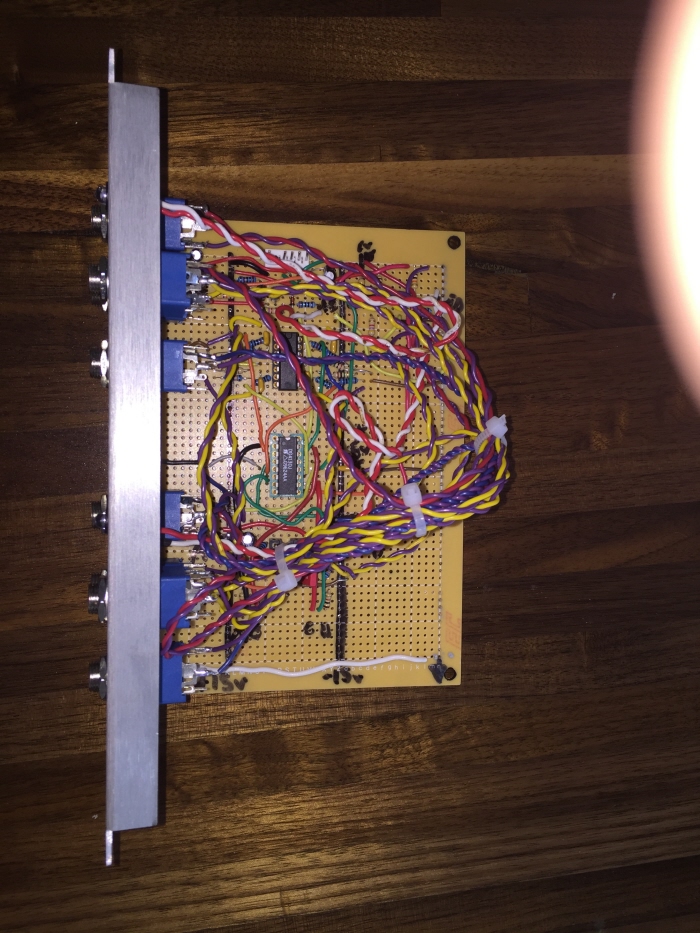
Perfboard prototype.

Perfboard prototype rear.

Test and debug by patching into my modular system. Initial build did not produce sound. I was able to trace through the circuit and locate an error with two transistors being wired to -15 volts instead of +15 volts. Then with the CV triggers A and B working I was able to trace through the input op amp circuit to find that the -15 volt rail was not properly soldered. When I fixed the fault, everything began to work perfectly!!! Time to fabricate the board into a 5U panel.

I have modified a template from Yusynth that I can use to mark the places that I need to drill holes for the 8 Jacks and 2 LEDs that will eventually mount to the face plate.

Slots for jacks and LED's are drilled.
Completed module with 5U panel, Jacks, LED's and a few cable ties to keep those twisted pairs nice and tidy.

This perfboard pcb was large enough that instead of using standoffs, I decided to mount it directly to the side of the 5U panel. Two flat screws attach the pcb flush against the extruded aluminum.

Almost finished. Those LED bezels look sharp! Since my white fine tip paint marker is all dried up, I'll label the jacks when when my new pen arrives in the mail.

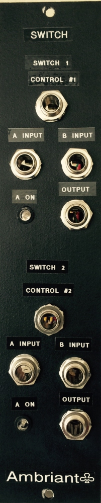
I have removed the paint marker with lighter fluid and I have used a label maker to add text. Looking much better!


gLike
Switch - Module
Control voltage, electronic analog switch. This is a custom design.
These switches can be used to switch between patches during a sound, oscillate between two different filter settings, switch between left and right outputs, etc.
Features;
* DC coupled. Works with both CV or Audio signals.
* LED status indicator High/Low
* Unity Gain Buffered Pass-through