
The core of the oscillator module will be an lm556 function generator ic.
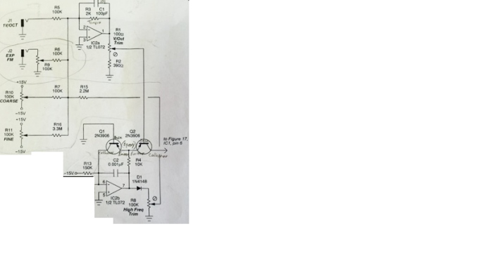
Schematic.
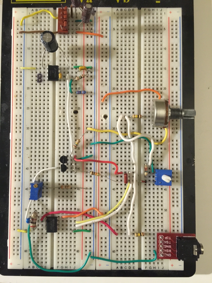
Initial breadboard build. Here I have implemented only the course tune. With only the course tune feature implemented, the unit tracks accurately for only half an octave. This was a discouraging result at first, until I re-read the schematic and decided to add the fine tune feature, as I suspected it would significantly improve tracking accuracy.

Here I have added an op amp which I have used to normalize the gain of each waveform output. Triangle and square outputs are accessible individually and simultaneously.

Notice the three silver pots. They are each 100k. They adjust course tune, fine tune and fm amount. I have added an additional input for the fm modulation. Everything tests fully functional. I am pleased with the performance, so I will move forward with perf boarding this into a useful module.
I've also experimented with a sine wave shaping circuit, which aims to shape a sine wave from the existing triangle wave. I am unhappy with the results, so I will eliminate this feature from the final build.

The first thing I do when working a perf board circuit is to create a ground path on the perimeter, a +15v rail, and a -15v rail. No 5v is required for this module. This will help me plan out the parts placement a little better.

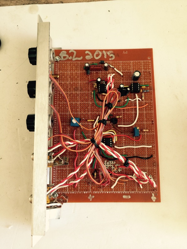
Top view where I have soldered all the components over to a perf board which will be placed inside of a module face panel. Everything meets performance expectations, as before on the breadboard.
I didn't have any tempco resistors laying around, so I shrank wrapped the two npn transistors back to back in hopes to prevent any temperature related pitch drift which might occur.

The completed perf board. Rear solder joints. Not perfect, but cheaper than ordering a pcb. Also much greater rewards are sown by accomplishing a DIY build.

Testing the unit for errors in construction.
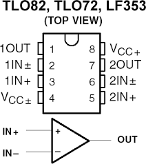
I used a single TL072 to buffer both the saw and square outputs of the lm566 ic. I had to increase the gain of the saw x 2 from 2.5 to +-5v. And I needed to decrease the gain of the square wave output from +-6v down to +-5v. The spec sheet states that the square wave output on the ic is +-5v, but I found it to be higher. I performed an a/b comparison against my synthesizer.com oscillator module to serve as a gold standard. I have matched the gain of each waveform to mach the .com standard of +-5 v.

This is a rather large perf board. I like using this size because it has a lot of real estate to work around in. Standoffs, wont work for this one, so I'll mount it to the inner side lip of the face plate.
I bore two holes on the side lip of the module and ensure that the screws sink flush, so as to ensure a tight fit inside the modular case.

Using a blank single panel, I use a drill press to forge holes for pots and jacks. This is actually a previous used board that used to be a Hexinverter distortion module. I didn't use the module, so I'm re-purposing it here, enlarging two slots to house two jacks instead of an LED and a spst switch.

Alternate view. Side.
Cable ties keep everything nice an neat.

Knobs are snug. Jacks are installed. Time for some paint marker.

I use a white fine tip paint marker to mark the function names onto the face panel. These letters wipe off with a cotton cloth and some lighter fluid. I can clear the crude text later on, and mill some proper text onto the panel someday. All and all, the unit tracks pitch very well, and I'm happy to have an additional oscillator to add to my modular system.

Using a label maker, I have added snazzy looking labels. The previous paint marker was wiped away with a cloth and lighter fluid.
gLike
VCO - LM566 Implementation
Implementing a voltage controlled oscillator using the LM556 ic as the module core.
Features:
* 1 v/octave pitch tracking
* Course tune
* Fine tune
* Exp. FM input
* Exp. FM amount
* 10v pp audio output