
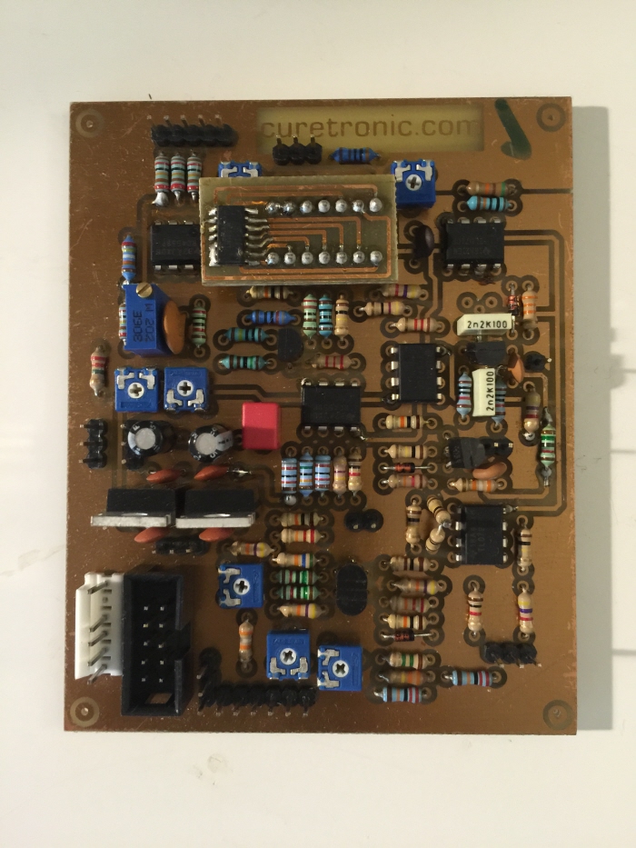
It arrived! All the way from Germany. I'm not yet certain what calibration will be required to get this oscillator to track voltage to pitch correctly, but I will find out soon enough when the module is together. Also, please note the pins on the board. I will need to use jumper wires instead of solder to connect my jacks and potentiometers to the pcb.

I'll be using the female ends of these jumper cables to plug into the pins of the PCB board. I'll cut off the male ends, strip the leads and then solder directly to my pots and jacks.

A rotary switch is used to select from five range selections.
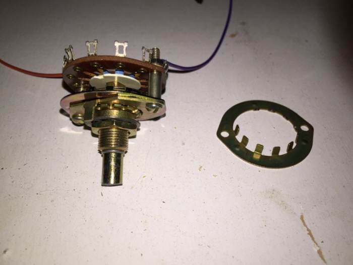
By clipping off some of the notches on this circular flange, I can set the maximum rotation of the switch.

My work area. The panavise is very useful when soldering jacks and pots. I use a fan to draw the solder flux smoke away from me while I work. I've been using a cheap Chinese solder iron, but it gets plenty hot enough and works very well. I don't use a wet sponge, ever. Instead I prefer to use the steel wool type tip cleaning solution.

I cut the male pins off the jumper cables, stripped the wires and soldered that end to the pots and jacks.

After I have wired all the jacks and pots, I like to test and debug the PCB before I commit to fabricating a panel. This time, I found errors with the Range rotary switch, and a few pots were completely shorted due to poor quality I presume. Once I discovered the fault with the defective pots, functionality began to meet my expectation.

Notice the female jumper cables which are used to connect to the male pins on the pc board. I liked using these jumper cables more than using the MTA connector cables that many manufacturers use. They were cheaper and I didn't need to crimp any wires into connectors.

I was able to locate a template that I found at YuSynth.net which I have used to mark the areas where I need to drill.

I'm fortunate to have a nice drill press in my shop.

I like to plan out the knobs I'm going to use. This way I know that my text will clear the pot diameter when I stencil in the function names.

Working with a fine tip paint marker is always a challenge. When I make mistakes, I rub it off with lighter fluid, and try again. Paint markers can smear and smudge and sometimes the paint can run.

Down to my last two cable ties. Doing my best to keep the wires tidy.

Finally finished! Sounds great. Works 100%. No issues.

I have redone the panel face text with a label maker. I use white on black tape.
gLike
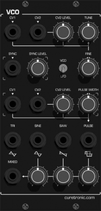
VCO - Voltage Controlled Oscillator Module
Curetronic 100m 112 VCO Assembled PCB
Features:
* Excelent tracking over a wide range
* Control for PITCH (fine tune)
* VCO range (2', 4', 8', 16', 32')
* 3 CV inputs with attenuators
* PWM control (min - 50%)
* PWM input with attenuator
* Sync input
* Strong/weak sync toggle switch
* Pulse, saw and tri outputs
* Dimensions: approx. 160mmx80mm, height 20mm
* Power requirements: +/-15V