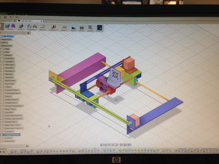
The full machine design was modeled in Autodesk Fusion 360 as a working assembly. This was my first project in Fusion (been working with SolidWorks for over 10 years) and I really like the program capabilities and how accessible it is.
I didn't have access to a CNC mill or router but I did have a 3D printer to print some of the more complicated parts.
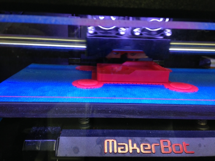
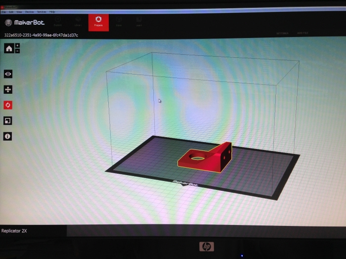
I made all the precision parts on the Makerbot Replicator 2X in ABS. This is the Z stepper bracket being printed.
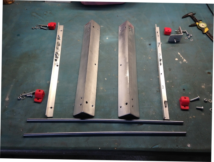
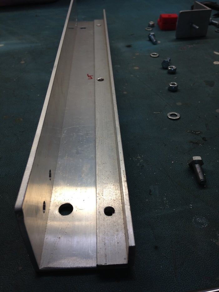
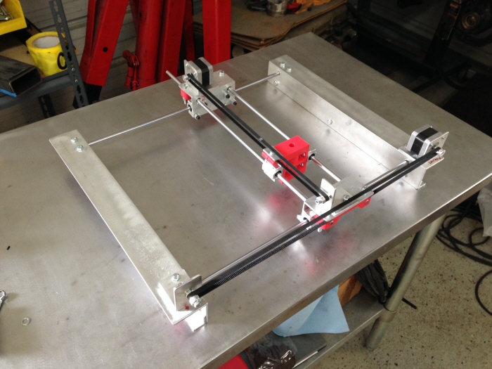
X-Y Frame parts laid out. You can see: 1.5" Aluminum Angle, 0.75 Aluminum Angle, 8mm Precision Rod, and Rod Holders
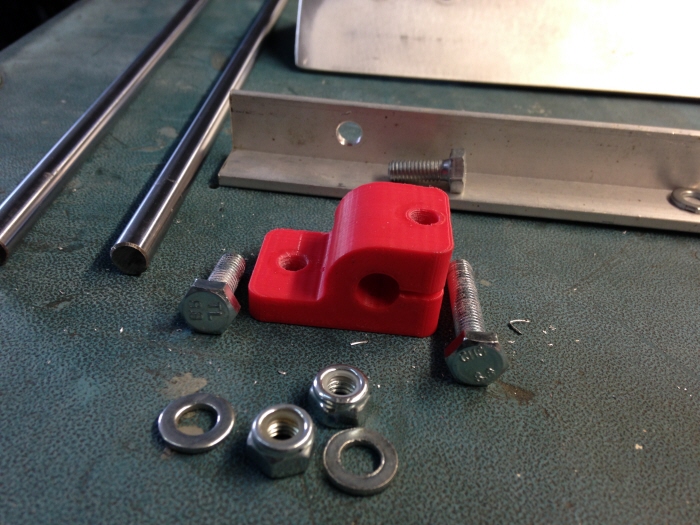
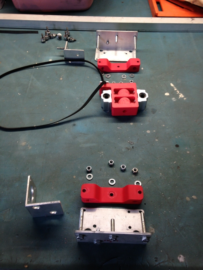
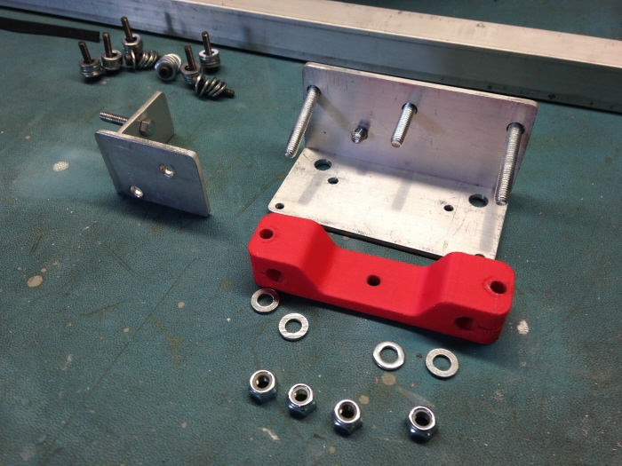
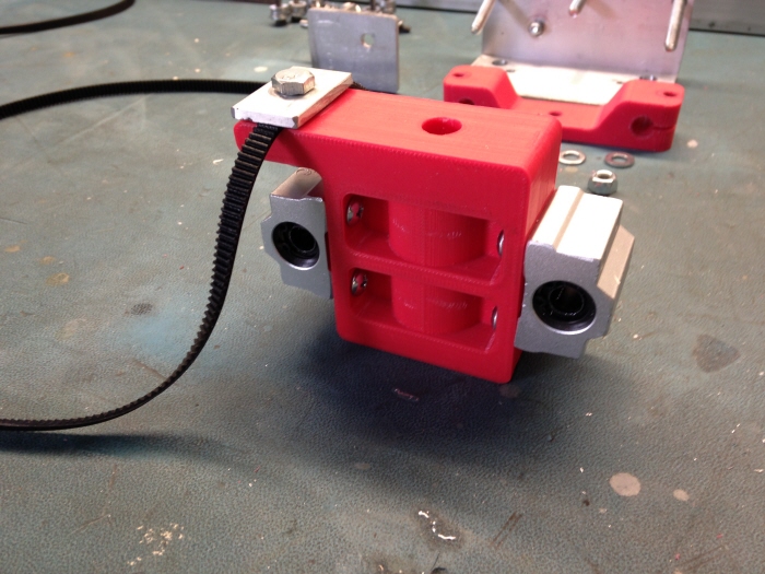
Close up of 3D printed Rod Holder. I wanted to simplify the design as much as possible so I incorporated one of the mounting holes with the tightening adjustment.
Rod Holder next to Idler Pulley Bracket
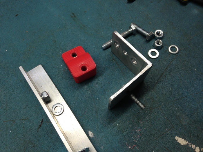
I attached the smaller aluminum angle to the 1.5" angle to provide a flange for clamping down if needed.
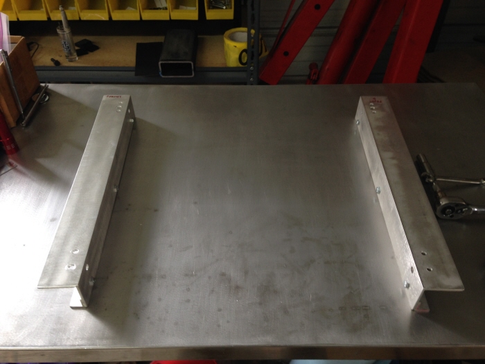
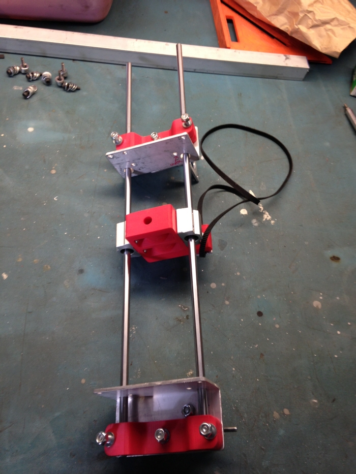
Left and right side frames.
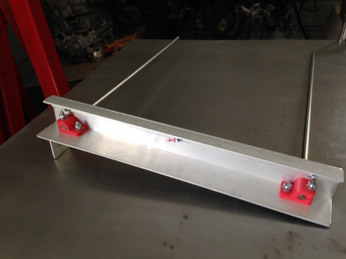
Attaching the 8mm precision rod.
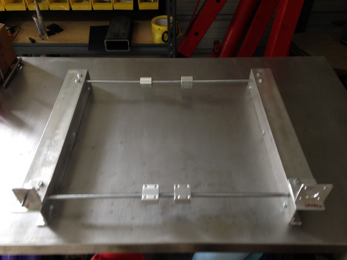
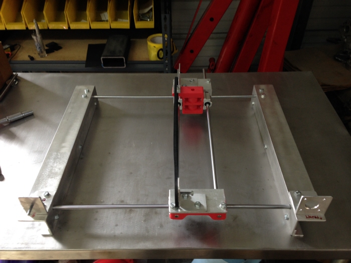
Both rails for the X-Axis slide are installed. You can see the 4 x SC8U linear bearings which attach to the Y-Axis platform.
Y-Axis slide ends shown with rod holders and Z block.
Close up of Y-axis rod holder. This is a one-piece design since the rails don't have a large span.
This was the first rev of the Z block. It basically only holds a pen without any control to raise or lower. I wanted to test and configure the X and Y axis before designing a variable Z.
Assembled Y-axis slide with Z block installed.
X and Y connected.
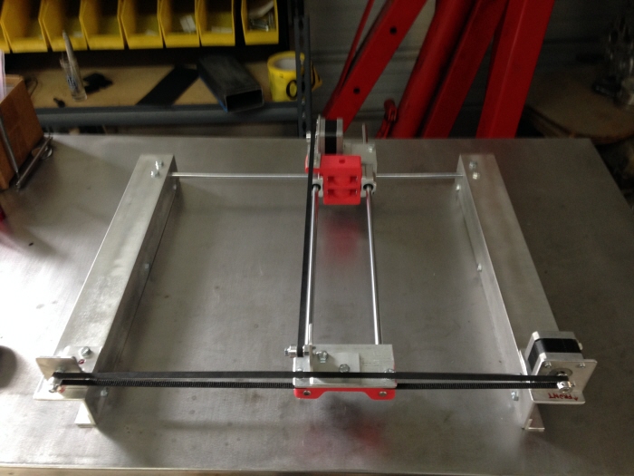
Steppers installed and timing belts routed.
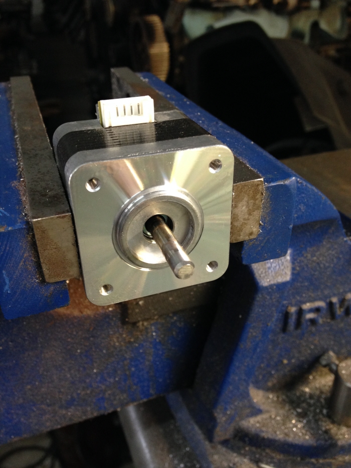
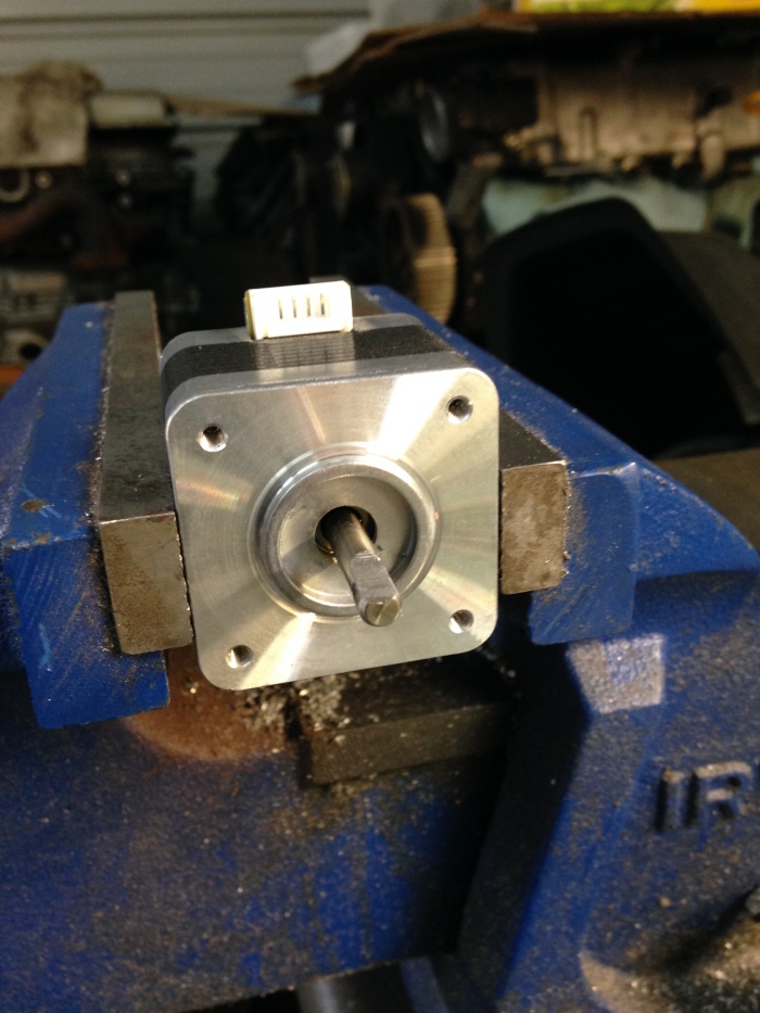
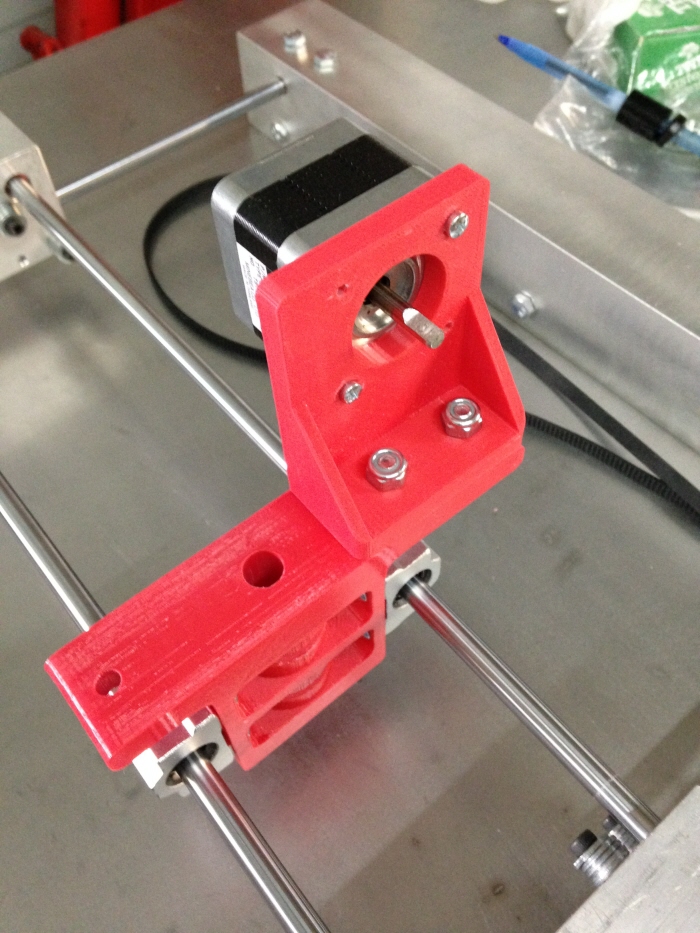
The Z stepper motor had a round shaft so I had to grind a flat to connect the actuator arm.
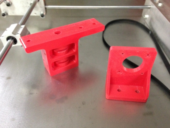
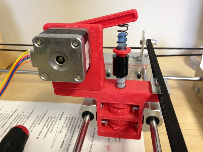
Here's rev 2 of the Z block and the Z stepper bracket. This uses a stepper motor with an actuator arm attached that presses down on the pen to engage it.
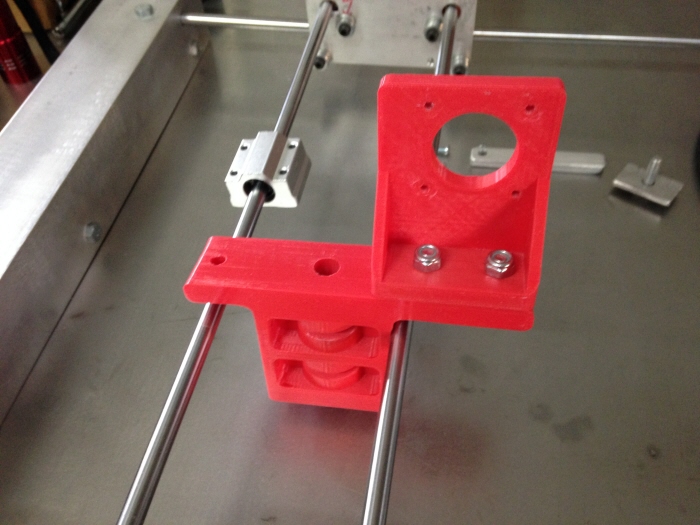
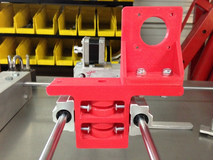
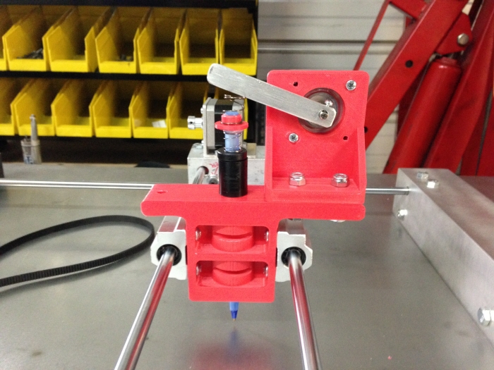
Stepper motor with actuator arm presses down on spring-loaded pen inserted into Z block. The bottom spring pushes the pen up when the arm disengages. When the arm engages it overpowers the weaker bottom spring and partially compresses the stronger top spring for consistent pen pressure on the drawing surface. This takes up any variability in the flatness of the surface it is drawing on.
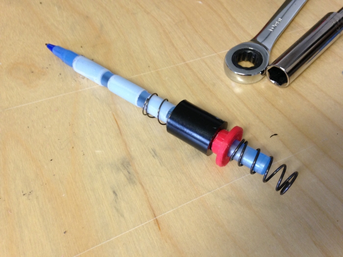
Spring loaded pen with precision tape applied :)
gLike
DIY CNC
Here's a personal project I took on to learn more about CNC machines and CAD to CAM programming. For the hardware I limited my budget to use mainly scraps from around my shop and common linear motion parts. Control hardware includes an Arduino UNO and CNC shield connected to three NEMA 17 stepper motors. Chilipeppr with GRBL interface controls it all.