

The main goal of this project was to develop hands-on experience in the field of robotics and micro-controllers by building a personalized robot from the base level

These criteria were chosen from the point-of-view of a recent graduate with a student budget looking to build a professional portfolio.

The following 6 variations of degrees-of-freedom were initially considered for the robotic arm.
Due to the fact that I did not have easy access to a workshop, I had to heavily base the design of the robot on bought-out parts. After extensive research on the availability of parts and components from online retailers such as SparkFun, Servocity, Radio Shack, in addition to Amazon and ebay, arrangement 5 was chosen due to the availability of suitable components that were within the stipulated budget range.

The major components that were used to build the prototype included:
- 2 sets of pan-tilt brackets
- 3 micro servo motors to facilitate the motion of 3 rotational joints
- 1 sub-micro gripper kit consisting of 2 gripper arms and a sub-micro servo mounting bracket
- 1 sub-micro servo motor to operate the gripper
- 1 Arduino UNO microcontroller
- 1 Nintendo Nunchuk
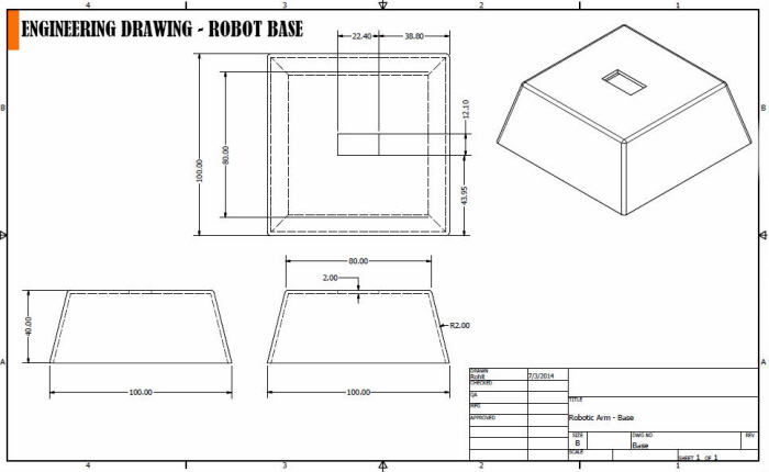
Autodesk Inventor was used to design a foundation / base upon which the robotic arm could be assembled.

The following images pertain to engineering drawings that were generated from 1:1 scaled 3D models of the major bought-out parts.These drawings were generated in order to be able to machine the parts if one had access to a workshop.


Major parts modeled using Autodesk Inventor.

The individual parts were then assembled using the Autodesk Inventor "Assembly" environment.
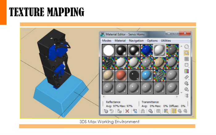
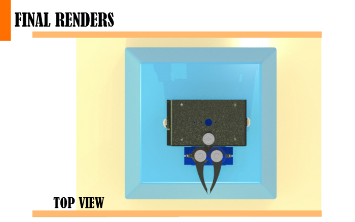
The assembly was then imported into Autodesk 3D Studio Max in order to map textures and materials onto the individual parts of the assembly, and generate rendered images of the robotic arm.


The first control method involved using a Nintendo Nunchuk to control each servo motor using I2C communication. Both, the joystick, as well as the accelerometer were initially tested to control each motor, and the joystick was found to enable better control and stability, particularly when the joints needed to be held at a certain orientation for a long period of time. The accelerometer also required the user to twist and turn his / her hand in ways that were at times, uncomfortable, due to which, the final control was based solely on the joystick. The horizontal "x" motion of the joystick was used to control joints 1 and 4, using the "z" button to toggle between the joints, and the vertical 'y" motion was used to control joints 2 and 3, using the "c" button to toggle between the joints.
Code from the following websites were adapted for use in this project:
- http://www.gabrielbianconi.com/arduinonunchuk/
- http://todbot.com/blog/wp-content/uploads/2007/11/bionic_arduino_class4.pdf
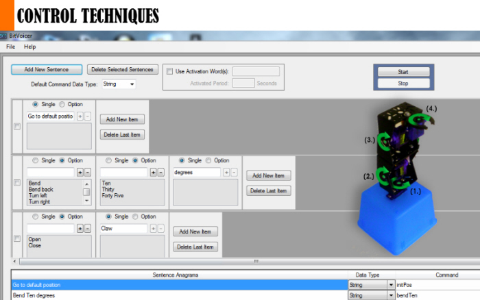
The second method involved integrating the Arduino IDE with a voice recognition software known as Bitvoicer, developed by a software development company called BitSophia. The software allows users to manually store sentences to be used as voice commands into a file known as a "Voice Schema". Each sentence is then assigned a "command" or associative keyword which the Arduino micro-controller receives through serial communication when the actual voice input is given. A user can then program the micro-controller to respond to the keyword that is communicated to it, based on the voice input.
Intuitive voice commands such as "Bend", "Turn", "Open Claw" and "Close Claw" were used to control each servo by specific degrees of rotation. Increments of 10, 30 and 45 degrees were used to move the joints of the robot to various positions to perform simple pick-and-place operations.

Tower Pro SG 90 micro servo motors were used for the rotational joints of the robot. From data sheets for these motors, the stall torque was found to be 1.8kgcm.
The equation to represent the torque acting at a point can be represented by:
T = F*d*sin(theta)
Where:
T = Torque applied
F = Force applied
d = distance between the force vector and point of application of torque
theta = Angle between the force vector and a vector from the point of application of the torque to the point of application of the force
In the given scenario, if the stall torque is substituted into the equation for variable "T", the force required to stall the motor can be calculated by plugging in values of 10cm and 135 degrees respectively, for variables "d" and "theta".
The force that was calculated was found to be 0.25 kg (0.55 lbs).
Thus, the weight of an object to be picked up by the robot from it's lowest bending position was required to be less than 0.25 kg or 0.55 lbs.

When the robot is standing perfectly straight with joints 2 and 3 at 90 degrees, the angle between the force vector (the vector representing the weight of the object being picked up) and joint 2 was approximated to be 25 degrees.
Using a similar substitution into the above torque equation, the the weight of an object that could be held in this orientation without stalling the motor was found to be 0.43 kg (~1 lb).

The final orientation that was considered, was a case where theta was taken to be 90 degrees.
In this case, substituting the given values into the torque equation yielded a stall force of 0.18 kg (0.4 lbs).
Overall, this was found to be the lowest possible force that could stall the motor.
The torque analysis was only carried out for the servo motor at joint 2, since the torque that was applied at this joint always either be equal to or more than the torque applied to the servo motor at joint 3. This was because joint 3 was closer to the point of application of the applied force, thus resulting in a lower applied torque.

Based on the Torque analysis, key parts and assemblies were chosen for an FEM analysis to analyze if the components would yield or deform upon applying a load of 0.4 lbs onto them.
It can be seen that the both - the Von Mises Stress, and the displacement due to the forces in all the cases, was found to be minimal.


gLike
Robotic Arm
The main idea behind this project was to make use of low-cost and easily available materials as a means to start working with robotics and micro-controllers.
The 3-DOF robotic arm was designed and modeled using Autodesk Inventor, and then assembled and prototyped. The arm can either be controlled by voice commands, or by using a Nintendo Nunchuk with the help of an Arduino Uno micro-controller.